
Scope of application
There are 15 varieties of three-phase flat coiliron core fully sealed distribution transformers with a capacity range of 30kVA-1000kVA.
The iron core is a three-phase three column inner and outer frame rolled structure. High degree of mechanization.
The high and low voltage coils are continuously wound on the iron core column, with good concentricity and compact coils.
The main technical and economic indicators have reached the international level of similar products.
Fully Sealed Distribution Transformer Model meaning

Get Free Quote of S13-M-30-2500/10 Fully Sealed Distribution Transformer
Execution standards
GB1094.1~2-2013 power transformer
GB1094.3-2003 power transformer
GB/T1094.4-2005 power transformer
GB1094.5-2008 power transformer
GB/T6451-2015 three-phase oil-immersed power transformer technical parameters and requirements International standard IEC76
GB/T25289-2010 Technical parameters and requirements of 20kV oil-immersed power transformer
Compared wth the “9” type transformer, this transformer has an average reduction of about 30% in no-load losses. Compared with the JB/T10088-1999 standard, the noise is relatively low, with a reduction of approximately 7dB. The temperature rise of the oil surface and high and low voltage windings is about 20K-13K lower than the temperature rise limit, and there is a certain overload capacity. Strong short-circuit resistance and high reliability.
Structural features
lron core: Adopting a three-phase three column internal and external frame rolling structure, the core column has a muti- level stepped circular cross-section After roling the iron core, stress is removed through vacuum annealing; Slot shaped bending dlamp, pulling screw to tighten the body, Apply special adhesive on the surface of the iron core to ensure that it does not deform or rust.
Winding and body: The low-voltage winding is a four layer or double layer cyindrical (500KVA and below) or spiral (630kVA and above) winding with 1-6 wires winding in parallel; The wires are all drawn with oxygen free copper; The interlayer insulation of the high and low voltage windings is made of diamond dot adhesive paper, The axial oil duct of the high-voltage winding and the oll gap between the high and low voltage main air ducts are of a strut curtain structure; The iron yoke insulation and trapezoidal cushion block are integrated to evenly compress the body of the device; The body adopts a new type of hanging plate positioning structure, with longitudinal and transverse positioning to ensure that the body is stable and not displaced.
Fuel tank: It adopts a corrugated oil tank sealed structure, which is non oil leakage and maintenance free.
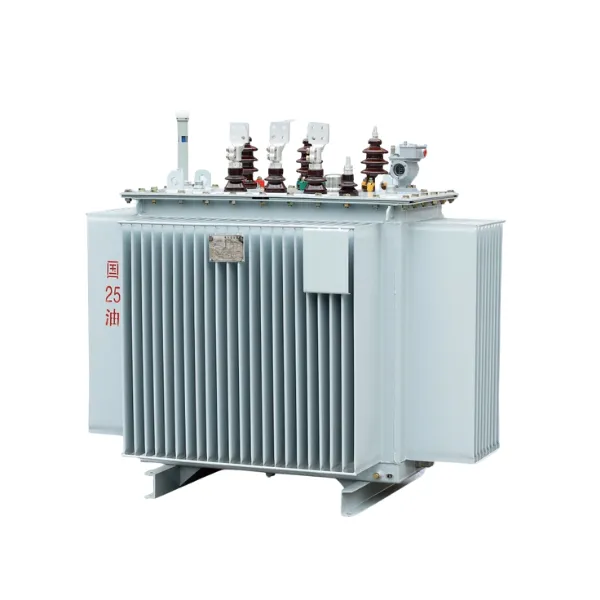
Main technical parameters
| Rated capacity kVA | No-load loss kW | Load loss kW |
| 30 | 0.0800 | 0.630/0.600 |
| 50 | 0.100 | 0.910/0.870 |
| 63 | 0.110 | 1.09/1.04 |
| 80 | 0.130 | 1.31/1.25 |
| 100 | 0.150 | 1.58/1.50 |
| 125 | 0.170 | 1.89/1.80 |
| 160 | 0.200 | 2.31/2.20 |
| 200 | 0.240 | 2.73/2.60 |
| 250 | 0.290 | 3.20/3.05 |
| 315 | 0.340 | 3.83/3.65 |
| 400 | 0.410 | 4.52/4.10 |
| 500 | 0.480 | 5.41/5.15 |
| 630 | 0.570 | 6.20 |
| 800 | 0.700 | 7.50 |
| 1000 | 0.830 | 10.3 |
| 1250 | 0.970 | 12.0 |
| 1600 | 1.170 | 14.5 |
| 2000 | 1360 | 18.3 |
| 2500 | 1600 | 21.2 |
Note:
1. The load loss value before the slash in the table applies to the Dyn11 or YZn11 coupling group, and the load loss value after thee slash applies to the Yyn0 coupling group.